Characteristics
- 6 to 20 MeV
- Sharp drop-off in dose beyond the tumor
- For treating superficial tumor (<5cm deep)
Production of the electron beam
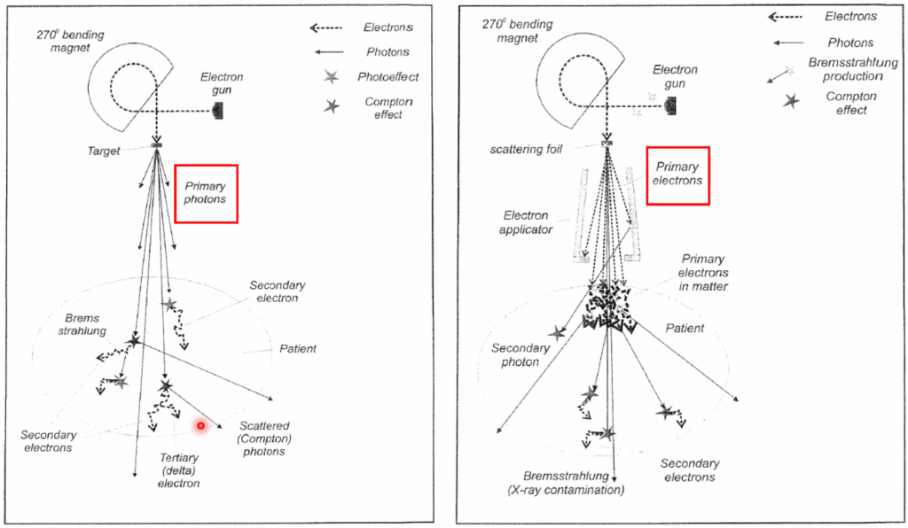
- Tungsten target 대신 scattering foil 사용
14.1 Electron Interactions
Coulomb force interactions
- Inelastic collisions → energy loss
- Atomic electron → Ionization and excitation
- Atomic nuclei → Bremsstrahlung (핵 근처에서 감속 된 E 만큼의 X-ray 발생)
- Elastic collisions → change direction
- Atomic electron → electron-electron scattering
- Atomic nuclei → nucelar scattering
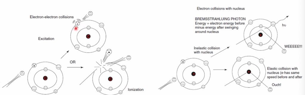
(왼쪽: electron과의 반응 / 오른쪽: nuclei와의 반응)
A. Rate of energy loss
A.1. Collisional losses (Ionization and Excitation)
- E loss ∝ electron density.
- Greater for low Z
A.2. Radiation losses (Bremsstrahlung)
A.3. Polarization
A.4. Stopping Power
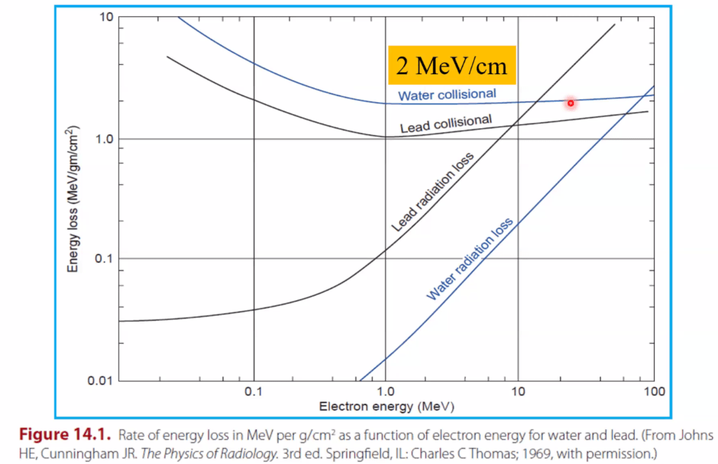
단위 길이당 energy loss
- 낮은 E에서는 low Z 에 의한 loss가 크지만,
높은 Z에서는 high Z에 의한 loss가 크다. - 정량화
- Mass stopping power (MeV-cm^2/g)
- Restricted stopping power
- Absorbed dose
- MeV/g <- ‘단위질량당 에너지’ = dose
- Collisional losses
- Electron to electron reaction
- Radiation losses
- Brehmstrahlung E로 나가는 등.
Electron bragg peak이 잘 나타나지 않는 이유: BP를 생성해도 방향이 제각각이고 금방 사라지기 때문에 합산이 안된다.
A.5. Absorbed Dose
Photon의 경우 stopping power 대신 attenuation coefficient를 이용한다.
B. Electron scattering
14.2 Energy Specification and Measurement
LINAC에서 처음 가속된 전자는 sharp한 monoE spectrum을 가질 것.
LINAC head의 scattering foil, monitoring chamber 등의 구조물을 지나면서 E가 변하게 된다. 두 번째 그래프 처럼 좀 퍼지게 된다.
Bending magnet을 통해 나오는 E는 이런 양상을 보인다.


A. Most probable energy
Peak 값 = “most probable energy”, Ep.
이건 surface에 대한 energy 이고, z에 들어가게 되면 더 퍼지게 된다.
아래는 typical depth dose parameters.
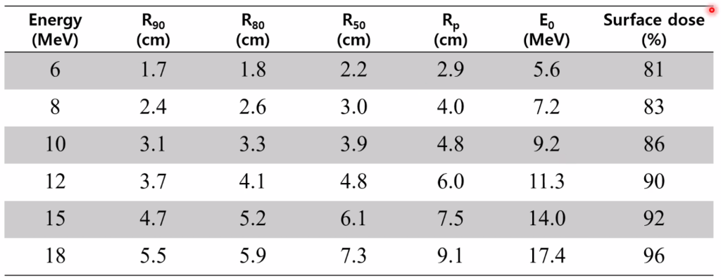
- How to approximate? “2, 3, 4, 5 rule”
- R100 = Dmax (E in MeV) x 2mm
R80 = Dmax x 3mm
R50 = Dmax x4mm
Rp = Dmax x5mm (= practical depth. 이 아래로는 전달되는 선량이 적다) - e.g., 6MeV 의 Dmax는 1.2cm. 90% 선량은 1.8cm까지 전달.
Energy specification
- Ez = E0 (1-z/Rp) : 시험문제 나오기에 좋다.
B. Mean energy
C. Energy at depth
Measurement
- Plane-parallel chamber (PP chamber, best suited)
- Cylindrical chamber
14.3 Determination of Absorbed Dose
Electron은 ion chamber에서 얻은 값과, 깊이에 따른 water to air stopping power ratio를 고려해야 한다.
A. Output calibration
B. Depth dose distribution
B.1. Ionization chambers
B.2. Silicon diodes
바로 depth-dose curve를 구할 수 있다는 장점이 있다. Silicon 과 water 간의 ratio간의 차이가 거의 없기 때문.
B.3. Film
B.4. Phantoms
14.4. Characteristics of Clinical Electron Beams
PDD가 제일 특성을 잘 보일 것.
일반적으로 2MeV/cm of water of soft tissue 만큼 energy loss
Dose decreases abruptly beyond the 90% of doses
Photon은 고에너지가 표면에서 더 낮다. 반면에 electron은 고에너지가 저에너지보다 굴절 각도가 작아서 scattering이 덜 일어나게 되어 표면에서 더 높은 에너지를 가지게 됨.
R90%(cm) = E/3.2
R80%(cm) = E/2.8


Photon과는 달리 skin sparing effect가 거의 없다.
E가 증가함에 따라 surface dose가 증가한다. Low dose는 scatter angle이 더 커서? ~를 당긴다.
A. Central axis depth dose
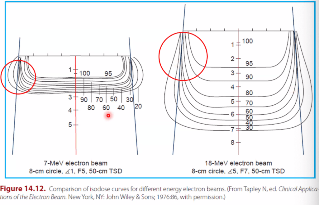
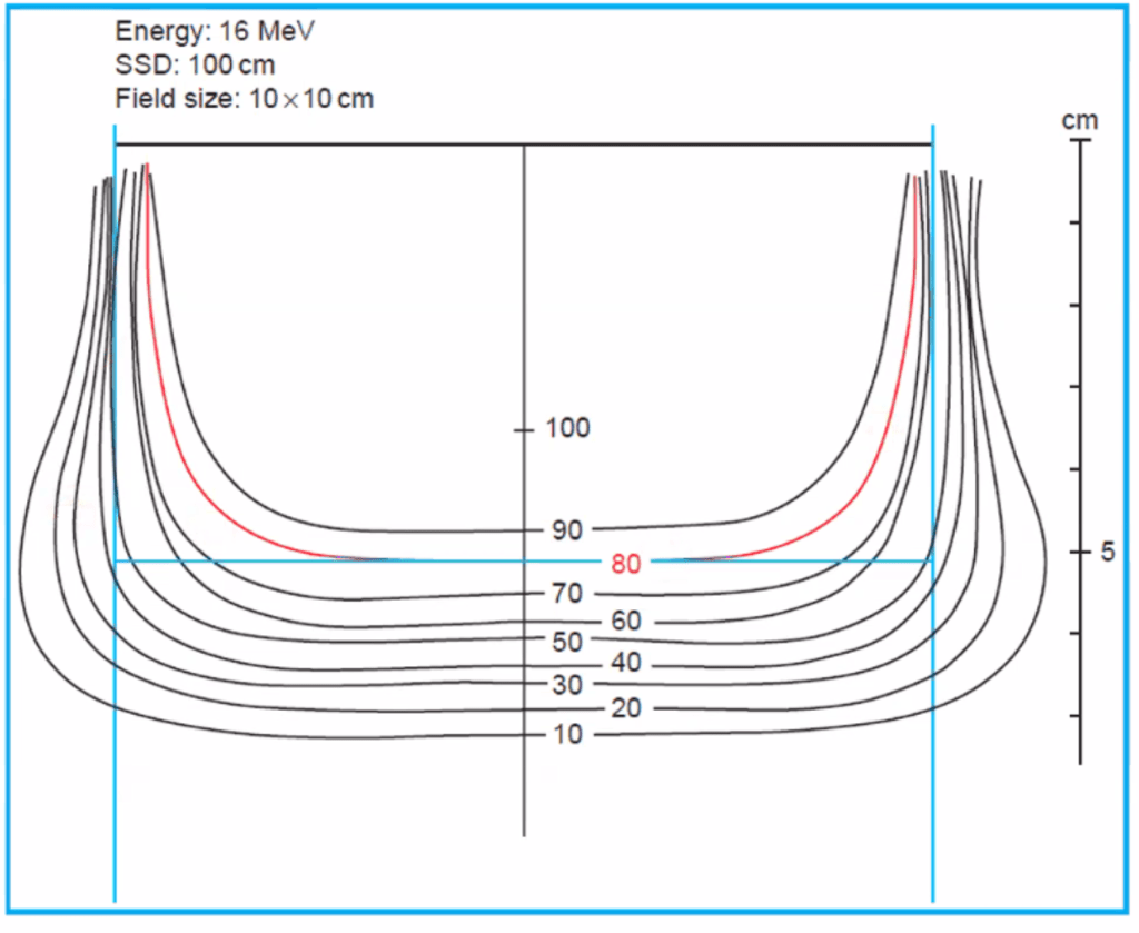
B. Isodose curves
- Low dose (7MeV)에서는 전반적으로 바깥으로 확장하는 형태를 보인다.
- High dose (18MeV)에서는 안쪽으로 들어오는 형태를 보여서, 설계시 유의해야 한다.
C. Field flatness and symmetry
C.1. Beam collimation
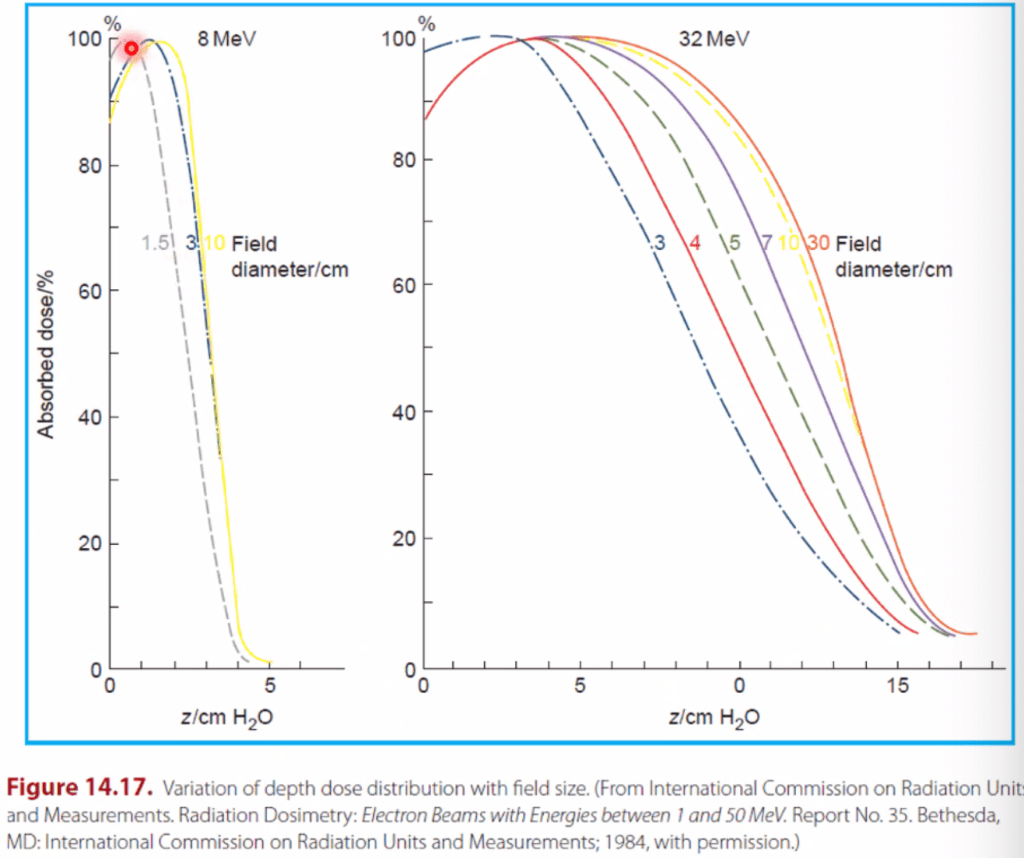
D. Field size dependence
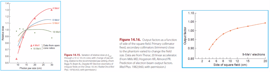
- Electron도 photon과 마찬가지로 output factor와 field size가 비례.
As field size increases, scattering proportion increases.
Low E 에서는 field size에 따른 변화가 크다.
(Fig 14.16) If field size > 6cm? 증가분이 적어진다. 옆에서 들어오는 깊이에 한계가 있기 때문. - Depth dose (penetrance) 도 다르다.
- Lateral scatter equilibrium (LSE) loss 때문.
- LSE를 위한 최소한의 field radius (R_eq)가 있다.
Req≈0.88 root(E_p,o)
- SSD가 증가할 수록 surface dose는 감소하고 therapeutic range는 증가한다.
- Effective SSD: field size와 E에 따라 달라진다.

E. Field equivalence
F. Square root method
G. Electron source
Photon은 scattering foil 등을 통해 퍼뜨리기 때문에 inverse square law를 잘 만족하지 않음(?) 이걸 만족하는 SSD를…
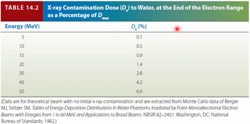
H. X-ray contamination
깊이가 깊어지면 contamination 형태로 들어가게 된다. 전체의 1% 미만이 들어갈 것.
clinical 하게 그렇게 중요하진 않음.
14.5 Treatment planning
A. Choice of energy and field size
보통 PDD graph에서 90% 선을 보게 된다. 6MeV라면 1.8cm까지 생각 할 것.
Isodose curve를 보면 안쪽 부분을 cover 하기 위해 margin을 1cm 까지 생각해둬야 함.
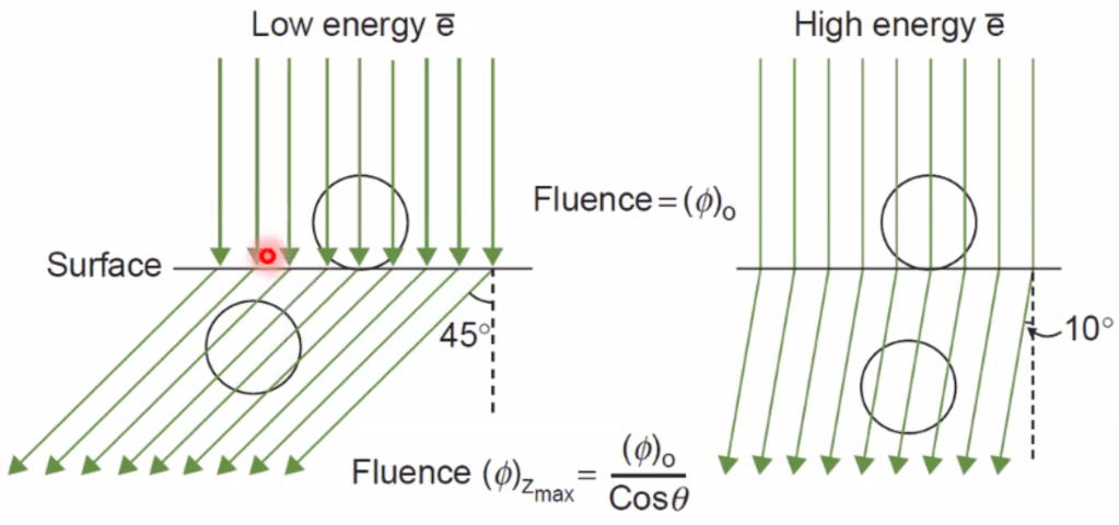
B. Corrections for air gaps and beam obliquity
Beam이 oblique 하게 들어가는 경우가 상당히 많다.
기울어질 수록 Dmax가 surface쪽으로 이동하며 penetration이 감소된다 (Side-to-side scattering이 많아지기 때문)
수평하게 들어갔을 때의 dose * (depth 차이만큼을 inverse square)
표면이 irregular 하면 hotspot들이 생성된다 → 3D volus 등을 이용해서 편평하게 만들어야 함.
- Beam obliquity
- Chest wall 처럼 급격한 변화가 있는 곳? 의 oblique 한 부분이 생길 때 선량분포의 변화를 고려필요
- If the beam obliquity is severe or the surface is not flat, using electron beam may not be appropriate.
- Obliquiqty tends to (a) increase side scatter at dmax, (b) shift dmax toward the surface, and (c) decrease the depth of penetration.
Air gap이 클 수록 surface쪽으로 당겨지며 penumbra 가 넓어진다. inverse sq law도 고려.

C. Tissue Inhomogeneities
- If there is bone on the way, hotspot may generated outward.
- CET (coefficient of equivalent thickness)를 사용하는 방법이 가장 많이 사용. 물의 density에 대한 계산.
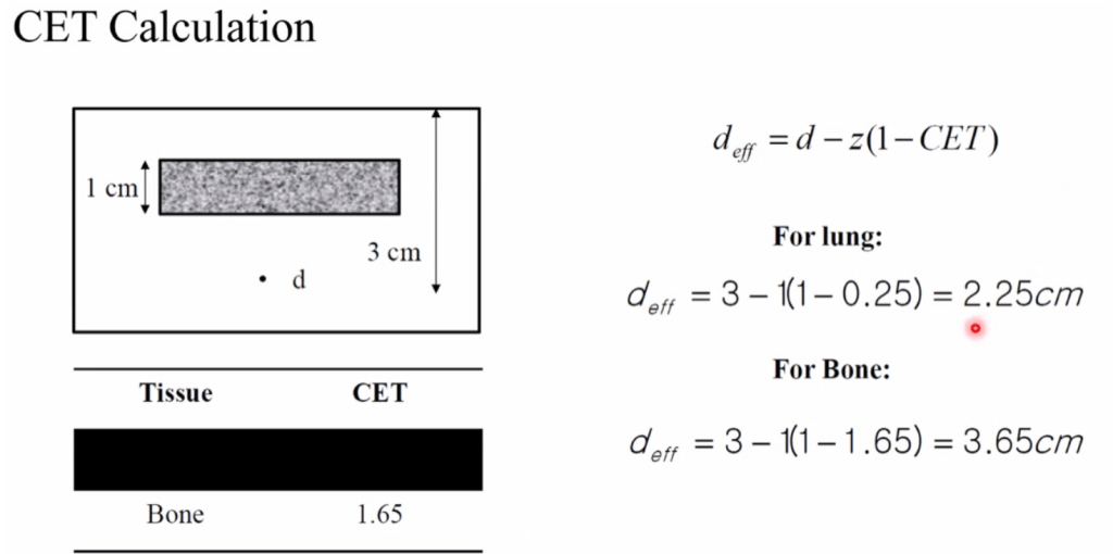
C.1. Bone
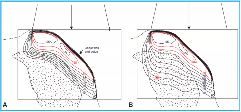
C.2. Lung
Lung 등을 지날 땐 상대적으로 penetration이 증가하여 더 깊이 들어가게 된다. 이걸 고려해서 planning 해야 함. Inhomogeneity를 고려했을 때에는 A → B 형태가 됨을 알 수 있다.
C.3. Small inhomogeneities
D. Use of bolus and absorbers
E. Problems of adjacent fields
14.6 Field shaping
- 보통 5% 이내로 beam이 들어가도록 shielding 하게 된다.
- 너무 얇게 대면 오히려 scattering 때문에 dose가 더 많이 들어가게 된다.
- Pb (mm) = Incient electron energy /2 +1
- 6MeV라면? 6/2+1 = 4mm
- Cerrobend (mm) = Pb (mm) x 1.2
- Pb 대신 많이 사용.
A. External shielding
Target 뒤로 방사선이 들어가는것을 방지하기 위해 사용.
(a) tungsten eye shield
- 이걸 쓴 상태로 CT 촬영 후, ~~ assign 해서 planning
(b)
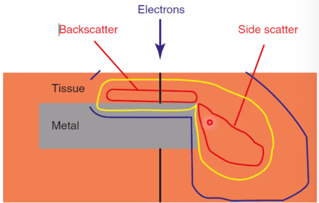
Back scattering
- Shielding 앞으로 dose가 많이 들어갈 수 있다.
- 이걸 줄이고자 앞쪽으로 absorber를 추가로 대서 back scattering을 줄인다.
- Absorber의 두께는 scatter 되는 E를 고려해서 결정해야 한다.
B. Measurement of transmission curves
C. Effect of blocking on dose rate
D. Internal shielding
- Aluminum cap 등을 이용하여 backscatter를 줄일 수 있다.
14.7 Electron arc therapy
A. Calibration arc therapy beam
B. Treatment planning
B.1. Beam energy
B.2. Scanning field width
B.3. Location of isocenter
B.4. Field shaping
B.5. Isodose distribution
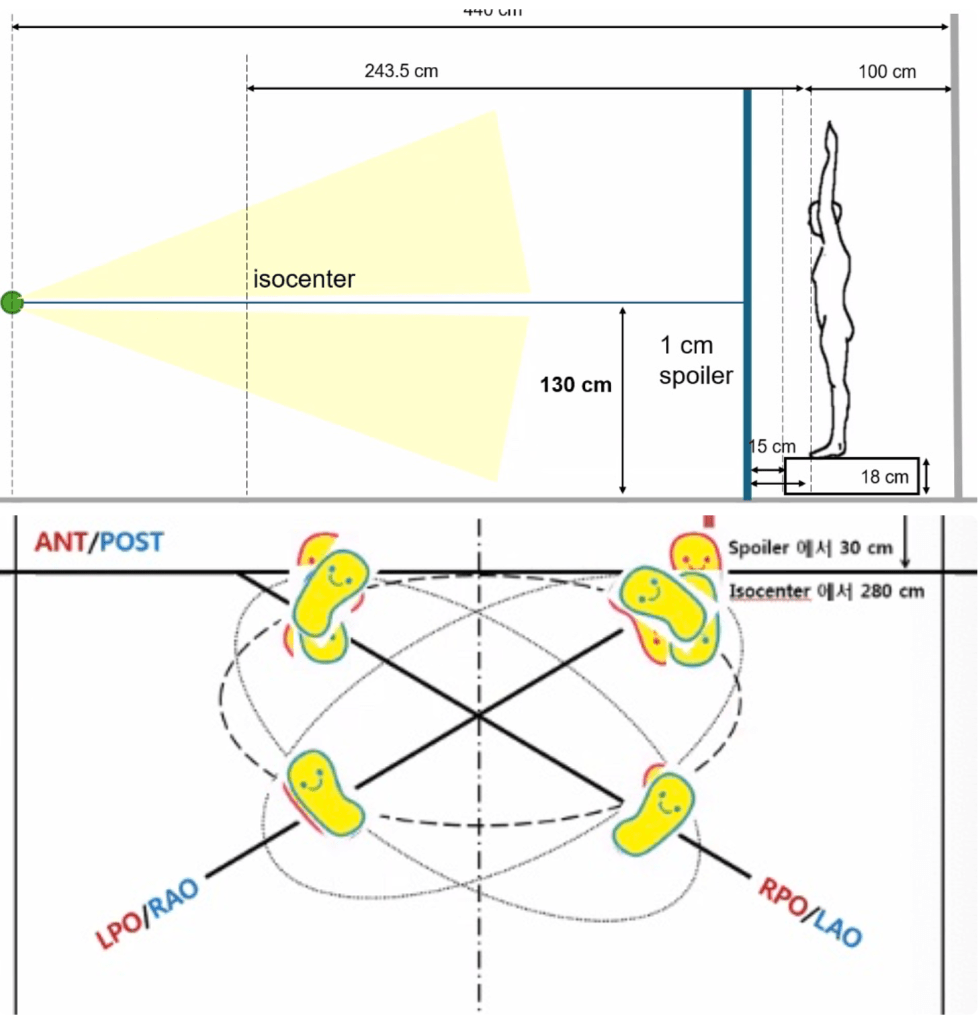
14.8 Total Skin Irradiation (TSI)
Indication
- Cutaneous T cell lymphoma (e.g, mycosis fungoides)
- Kaposi sarcoma
- SNUH
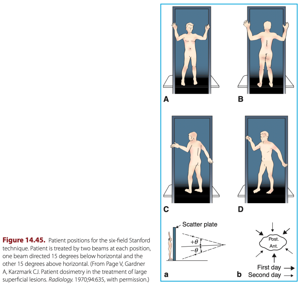
- Dual beam, 6개 field를 사용하는 Stanford technique 사용 (large field)
- Dose rate 2500 MU/min (maximum)
- OSLD를 붙였고, 눈 손톱과 발톱에 shielding.
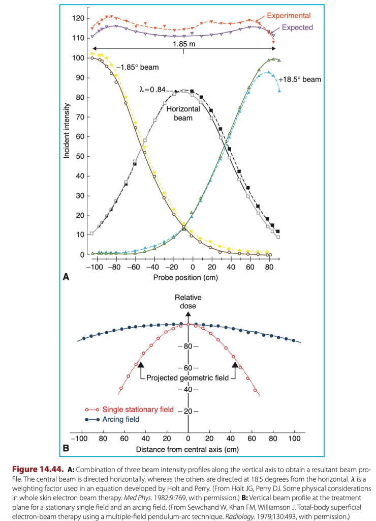
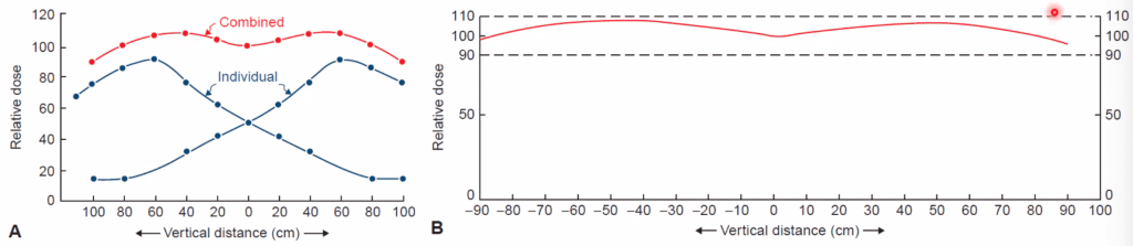
Extended SSD 형태로 beam을 조사하게 됨. 전신의 dose uniformity가 +- 10% 정도 되도록 설정.
A. Translational technique
B. Large field technique
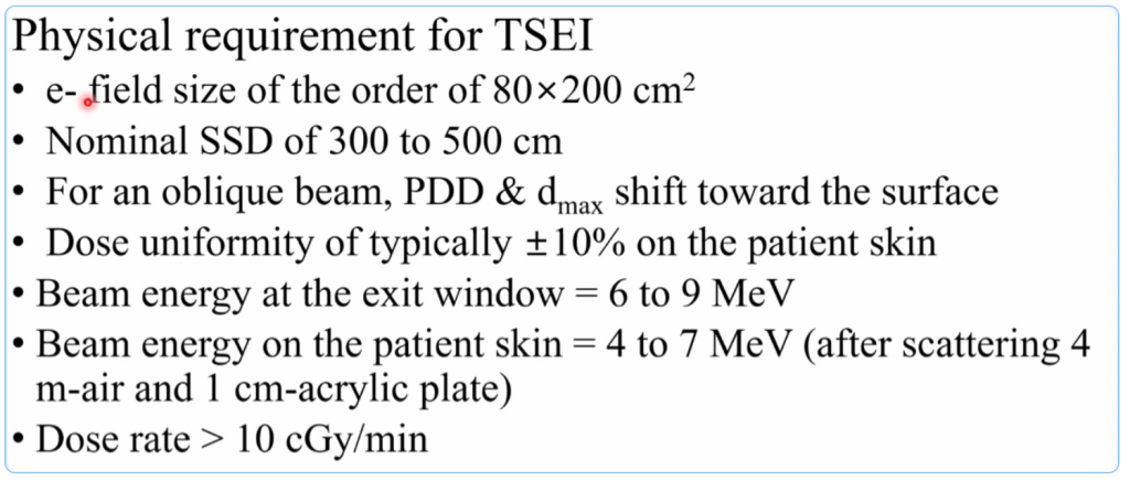
6MeV 사용 중.
B.1. Field flatness
B.2. X-ray contamination
B.3. Field arrangement
B.4. Dose distribution
- 200cm 이내에 ±10% ?
- Electron은 투과가 많이 안되기 때문에 곂치는 부분 (axilla) 등은 boost가 필요하게 된다.

C. Modified stanford technique
C.1. Dual-field angle
C.2. Calibration
C.3. In vivo dosimetry
14.9 Treatment-planning algorithms
A. Pencil beam based on multiple scattering theory
Using Gaussian function → Gaussian distribution
A.1. lateral spread parameter, sigma
Cut out 측정
- block shape이 square나 circular 하지 않은 경우 계산을 위해.
- MU 값을 계산하게 된다.